Systemy laserowe
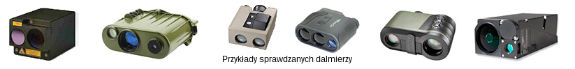
Systemy laserowe (dalmierze laserowe, oznaczniki laserowe, odbiorniki laserowe, laserowe urządzenia śledzące, wskaźniki laserowe, urządzenia laserowe) choć są jedną z kluczowych technologii w sektorze obrony/bezpieczeństwa, to znalazły masowe zastosowania również poza nim. Testowanie systemów laserowych jest potrzebne producentom, warsztatom serwisowym i ostatecznym użytkownikom. Zaawansowana aparatura pomiarowa może znacznie pomóc w produkcji, konserwacji, szkoleniach, optymalizacji zakupów i wykorzystaniu systemów.
Inframet oferuje serię stacji pomiarowych do testowania systemów laserowych: LTE, LTF, LJT120, L64, LIP, LT, LAS, JALI, LMOB, LBOR.
 |
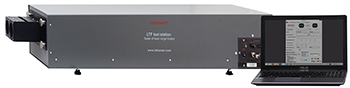 |
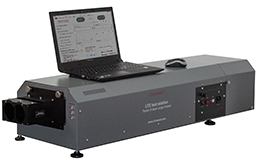
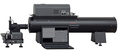
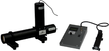
| Stacja pomiarowa LTE | Stacja pomiarowa LTF |
 |
 |
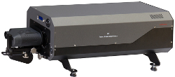
| Stacja pomiarowa LJT120 | Stacja pomiarowa L64 |
 |
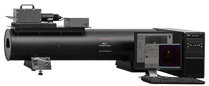 |
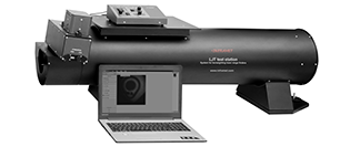
| Stacja pomiarowa LIP | Stacja pomiarowa JALI |
 |
 |
| Stacja pomiarowa LIS | Stacja pomiarowa LAS |
 |
 |
| Stacja pomiarowa LMOB | Stacja pomiarowa LBOR |
| Typ | Budowa | Możliwości pomiarowe | Przeznaczenie |
|---|---|---|---|
| LTE | System do pomiaru parametrów impulsów emitowanych przez nadajnik badanego dalmierza, generator krótkich impulsów optycznych (dwie metody: symulacja elektroniczna lub symulacja światłowodowa) | Energia impulsu, szerokość impulsu, częstotliwość impulsu, rozbieżność wiązki, czułość odbiornika, dokładność pomiaru odległości, błędy zjustowania, współczynnik ekstynkcji | Ultra-zaawansowany, uniwersalny tester dalmierzy laserowych lub oznaczników laserowych do projektów badawczo-rozwojowych, warsztatów naprawczych, kontroli jakości produkcji LRF i oznaczników laserowych |
| LTF | Generator krótkich impulsów za pomocą skalibrowanego kanału światłowodowego | Współczynnik ekstynkcji, dokładność pomiaru odległości, dyskryminacja odległości (opcja), sprawdzanie zjustowania | Doskonałe narzędzie do końcowej kontroli jakości LRF |
| LJT |
LJT generuje trzy zachodzące na siebie obrazy: 1) plamkę emitowanego lasera, 2) krzyż celowniczy, 3) detektor odbiornika. |
Zjustowanie nadajnik / odbiornik / kanał celowniczy. | Doskonałe narzędzie dla producentów, montażystów lub warsztatów naprawczych |
| L64 | Generator krótkich impulsów optycznych o regulowanych parametrach z wykorzystaniem generatora elektronicznego opartego na diodzie laserowej | Sprawdzanie czułości i zjustownia odbiorników dalmierzy laserowych lub trackerów laserowych | Doskonałe narzędzie do testowania odbiorników dalmierzy laserowych i trackerów laserowych |
| LIP | System do mierzenia parametrów wiązek emitowanych przez wskaźniki laserowe / oświetlacze, który jest w stanie mirzeyć wiązki o bardzo szerokim zakresie kąta rozbieżności wiązki i mocy | Moc, rozbieżność | Doskonałe narzędzie do testowania wskaźników laserowych i oświetlaczy laserowych |
| LIS | Stacja LIS może być uważana za wysoce uproszczoną wersję stacji LTE | Stacja jest zoptymalizowana do testowania określonego typu LRF, ale można przed zakupem zdefiniować parametry testowanego LRF. | Zoptymalizowany do testów serwisowych. |
| JALI | System do testowania i justowania laserów podczerwonych - z zakresu termicznym | Bardzo dokładny pomiar kąta rozbieżności, stabilności czasowej i przestrzennej | Profesjonalny system do testowania i justowania laserów podczerwonych |
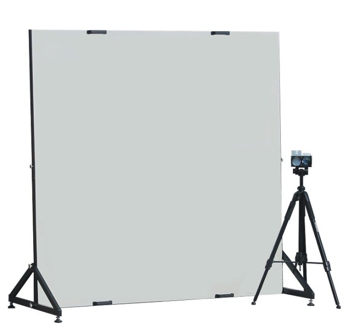
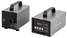
| LAS | System umożliwiający pomiar zasięgu lub współczynnika ekstynkcji ER w warunkach polowych | Zakres operacyjny, współczynnik ekstynkcji ER | Zalecane do testowania LRF w warunkach polowych lub w celu sprawdzenia poprawności działania stacji testowych klasy laboratoryjnej. |
| LMOB |
Symulator zmiennej odległości do testowania elektroniki odbiorników dalmierzy laserowych |
Dokładność pomiaru odległości | Testy terenowe LRF |
| LBOR |
Przenośny tester do justowania nadajnika dalmierza laserowego względem celownika optycznego lub kamery wideo VIS-NIR |
Błędy zjustowania |
Testy terenowe LRF zamocowanych na pojazdach mechanicznych |
Dowiedz się więcej: