Obrazowanie VIS-NIR
Kamery VIS-NIR są wrażliwe na promieniowanie widzialne i bliskie podczerwieni. Kamery VIS-NIR są zwykle przetwornikami zbudowanymi z krzemowych półprzewodnikowych sensorów, produkowanych w dwóch konkurencyjnych technologiach: CMOS i CCD. Jednak coraz większa liczba kamer VIS-NIR wykorzystuje sensory zbudowane przy użyciu niestandardowych technologii: zintensyfikowanego CCD (ICCD), zintensyfikowanego CMOS (ICMOS), CCD z powielaniem elektronów (EM CCD), EBAPS, bombardowany elektronami CMOS (EBCMOS), CMOS z płytką mikrokanalikową (MCPCMOS), scientific CCD (sCCD), sctientific CMOS (sCMOS).
Do pomiarów technologia produkcji sensora nie ma znaczenia, a różnice między różnymi typami sensorów stosowanych w kamerach VIS-NIR nie będą tutaj omawiane. Ważniejszy jest podział kamer VIS-NIR ze względu na standard obrazu. Znakomita większość kamer VIS-NIR generuje obraz elektroniczny za pomocą dwóch analogowych standardów wideo: PAL lub NTSC. Jednak coraz więcej kamer VIS-NIR korzysta z różnych standardów cyfrowych: Camera Link, GigE, LVDS, SDI, DVI, HD-SDI, HDMI, AHD, HD-TVI, HD-CVI, CoaXPress, USB2.0, USB3.0 , Ethernet. W praktyce oznacza to, że do przechwytywania i zbierania klatek z kamer VIS-NIR obecnych na rynku potrzebne są różne programy.
Terminologia technologii obrazowania VIS-NIR nie jest ustandaryzowana i dla tych kamer stosuje się serię różnych nazw: kamery CCD (w przeszłości większość kamer VIS-NIR stanowiły kamery CCD), kamery telewizyjne (kamery VIS-NIR mogą być traktowane jako następcy klasycznych starych kamer telewizyjnych), kamer dzienne (kamery VIS-NIR są najczęściej używane w warunkach dziennych w przeciwieństwie do kamer termowizyjnych używanych w warunkach nocnych), kamery do widzenia maszynowego (prawie wszystkie kamery używane w zastosowaniach widzenia maszynowego to kamery VIS-NIR).
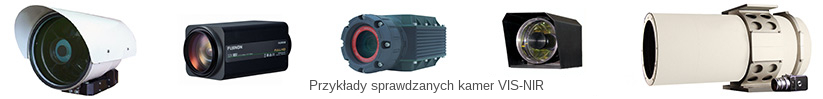
Kamery VIS-NIR znalazły szeroką gamę zastosowań i są produkowane na całym świecie w bardzo dużych ilościach. Ta strona koncentruje się głównie na testowaniu wysokiej klasy kamer obserwacyjnych. Są to drogie kamery VIS-NIR zintegrowane z dużymi obiektywami zoom, które umożliwiają obserwację dalekiego / średniego zasięgu i są wykorzystywane w zastosowaniach obronnych, ochronie ważnej infrastruktury, operacjach poszukiwawczo-ratowniczych i ochronie środowiska. Kamery VIS-NIR są często niedoceniane w porównaniu do kamer termowizyjnych. Jednak okazały się one cennym narzędziem w obserwacjach dalekiego zasięgu ze względu na ich zdolność do dostarczania kolorowych obrazów o wysokiej rozdzielczości w regulowanym polu widzenia, przy zachowaniu wielkości, masy i ceny kilka razy mniejszej w porównaniu do kamer termowizyjnych o podobnym polu widzenia. Najlepsze kamery VIS-NIR mogą działać skutecznie zarówno w dzień, jak i w nocy. Pomiary parametrów wydajności w ekstremalnych warunkach oświetlenia, są uważane za kluczowe dla prawidłowej oceny tych wysokiej klasy kamer obserwacyjnych.
Testowanie i ocena wysokiej klasy kamer VIS-NIR dla monitoringu dużego / średniego zasięgu praktycznie nie jest ustandaryzowana. Istnieje kilka nowoczesnych standardów wydanych przez organizacje międzynarodowe (European Broadcasting Union, European Machine Vision Association, British Standards Institution), które regulują testowanie kamer VIS-NIR w trzech konkretnych aplikacjach cywilnych (telewizja, widzenie maszynowe, monitoring CCTV), ale nie ma standardów, które regulują testowanie i ocenę omawianych tu kamer wojskowych VIS-NIR. W tej sytuacji testy wojskowych kamer VIS-NIR są zwykle wykonywane przy użyciu zmodyfikowanej metodologii testowania kamer termowizyjnych. Źródła światła zastępują ciała czarne w systemach pomiarowym. Minimalny rozróżnialny kontrast zastępuje minimalną rozróżnialną różnicę temperatur jako główny parametr. Istnieje również kilka innych różnic.